
In every IPIO unit there are four wired physical inputs and four virtual inputs. The virtual inputs are compatible with SIGFOX sensors and are profiled in another blog post. In this post we are drawing attention to the four wired physical inputs.
The input connector block is accessed by opening the lid of the IPIO unit. The input block is not pre-wired. There are two common ports and a four input ports. The IPIO input circuit has a built-in voltage of 3.5v.
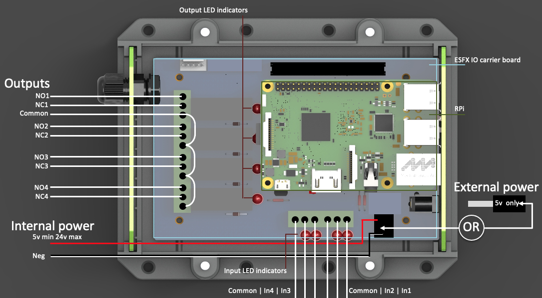
IPIO unit with lid removed
To fire an input a circuit should be made between the common and an input port. Primarily the input ports are designed to work with magnetic door sensors. Many installers use inputs not just as state indicators but also as start point points for rule-based behaviours. An input can be used to build an “if this then that” style rule.
We are not always aware of what ingenious functionalities installers have set up with IPIO, but know that there are many and varied applications: Here is a list of some frequently used set ups:
Gate activation – input detects either a gate open or gate close event
Gate state – sensor detects if the gate is closed
Kill buttons – input detects if kill button is switched and then fires an output to stop a process
Intruder alarm – set/unset
Over temperature – a temperature sensor trips to fire an output that stops a process
CCTV status – input detects armed or disarmed
Power monitoring – power level sensor fires an output to start recharging
Container door state – door sensor
Timer clock – input from timer switch fires an output to start a process
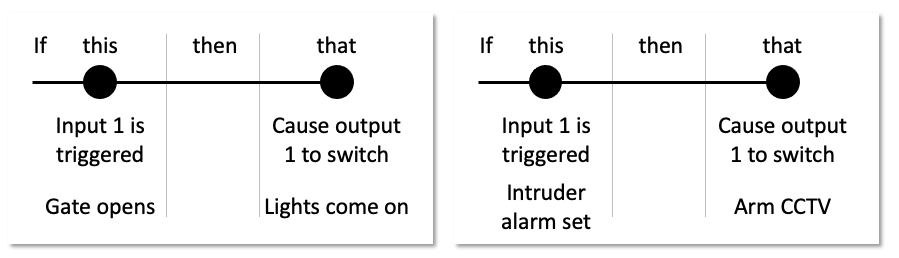
Input example cards